Join IoT Central | Join our LinkedIn Group | Post on IoT Central


Devices (332)

As industrial organizations connect more devices, enable more remote access, and build new applications, the airgap approach to protecting industrial networks against cyber threats is no longer sufficient. As industries are becoming more digital, cyberattacks are getting more sophisticated, and yet many organizations are lagging in the adoption of updated and reliable industrial cybersecurity postures. And when these organization’s security leaders start building a strategy to secure operations beyond the industrial demilitarized zone (IDMZ), they realize it might not be as simple as they thought.

Industrial assets (as well as industrial networks, in many cases) are managed by the operations team, which is typically focused on production integrity, continuity, and physical safety, rather than cyber safety. The IT teams often have the required cybersecurity skills and experience but generally lack the operations context and the knowledge of the industrial processes that are required to take security measures without disrupting production.

Building a secure industrial network requires strong collaboration between IT and operations teams. Only together can they appreciate what needs to be protected and how best to protect it. Only together can they implement security best practices to build secure industrial operations.

Enhancing the security of industrial networks will not happen overnight: IT and operations teams have to build their relationship; new security tools might have to be deployed; networks might need to be upgraded and segmented; new correlation policies will have to be developed.

Security is a journey. Only a phased and pragmatic approach can lay the ground for a converged IT/OT security architecture. Each phase must be an opportunity to build the foundation for the next. This will ensure your industrial security project addresses crucial security needs at minimal costs. It will also help you raise skills and maturity levels throughout the organization to gain wide acceptance and ensure effective collaboration.

Being the leader in both the cybersecurity and industrial networking markets, we looked at the successful projects Cisco has been involved in. This led us to recommend a three-step journey outlined in Cisco’s Industrial Security Validated Design.

What is a Cisco Validated Design (CVD)? CVDs provide the foundation for systems design based on common use cases or current engineering system priorities. They incorporate a broad set of technologies, features, and applications to address customer needs. Each one has been comprehensively tested and documented by Cisco engineers to ensure faster, more reliable, and fully predictable deployment.

Our approach to industrial security is focused on crucial needs, while creating a framework for IT and operations to build an effective and collaborative workflow. It enables protection against the most common devastating cybersecurity threats, at optimized cost. And provides a practical approach to simplify adoption.

To learn more, read our solution brief or watch the replay of the webinar I just presented. A detailed design and implementation guide will be available soon for helping to accelerate proof-of-concepts and deployment efforts.

Originally posted HERE.

Read more…
Fig.1 Arrow Shield 96 Trusted Platform

Introduction

IoT product development crosses several domains of expertise from embedded design to communication protocols and cloud computing. Because of this complexity “end-to-end” or “edge-to-cloud” IoT security is becoming a challenging concept in the industry. Edge in many cases refers to the device as a single element in the edge-to-cloud chain. But the device must not be regarded as a whole when security requirements are defined. Trust must first be established within the processing unit and propagated through several layers of the software stack before the device becomes a trusted end node. Securing the processor requires to properly integrate multiple layers of security and use security features implemented in hardware. Embedded security expertise and experience is required to accomplish such tasks. It is very easy to put a lot of effort on implementing security for an IoT product and in the same time missing to cover key use cases. A simpler way to narrowing down on defining the end-to-end security is to start with identifying the minimum set of business requirements.

Brand image, how a company’s customers perceive and value it, is one of the most valuable assets of any corporation. Two of the most important characteristics of an IoT device that can promote a positive brand image are: resiliency and privacy. For resiliency, this might mean adding features that increase the device’s ability to self-recover from malfunctions or cyber-attacks. For privacy, this means protecting user information and data but also the intellectual property (IP), the product invested in the product. This means that preventing exploitation through vectors such as product\device cloning and over production becomes important. Another business driver is the overall cost of ownership for the product. Are there security related features that can drive the cost down? We include here not just operational cost but also liabilities.

In this blog, we dive deeper into solutions that support these business requirements. We will also discuss a demo we have created in collaboration with our partners Sequitur Labs and Arrow to demonstrate a commercially available approach to solving a number of several security use cases for IoT.

Security in depth – a methodical approach for securing connected products

IoT security must start with securing the device, so that data, data collection, and information processing can be trusted. Security must be applied in layers and facilitate trust propagation from the silicon hardware root of trust (HWRoT) to the public/private cloud or the application provider back-end. Furthermore, the connected paradigm provides the opportunity to delegate access control and security monitoring in the cloud, outside of the device. Narrowing down further, device security must be rooted by enabling fundamental capabilities of the processor or system on chip and consider all three stages of the device lifecycle: inception (manufacturing, first boot), operation, and decommissioning.

In a nutshell we should consider the following layers for securing any IoT product:

  • Set a hardware root of trust – secure programming and provisioning (firmware, key material, fuses)
  • Implement hardware enforced isolation – system partitioning secure / non-secure
  • Design secure boot – authenticated boot chain all the way to an authenticated kernel
  • Build for resiliency – fail-safe to an alternative firmware image and restore from off-board location
  • Enable Trusted Execution – establish a logical secure enclave
  • Abstract hardware security – streamline application development
  • Enable security monitoring – cloud based, actionable security monitoring for a fleets of devices

These capabilities provide a foundation sufficient to fulfill the most common security requirements of any IoT product.

Embedded security features needed to build the security layers described above are available today from many silicon providers. However, software is needed to turn these into a usable framework for application developers to easily implement higher layer security use cases without the need for advanced silicon expertise.

Such software products must be architected to be easily ported to diverse silicon designs. Secondly, the software solution must work with the established IoT manufacturing process. “Turning on” embedded security features triggers changes to existing manufacturing flows to accommodate hardware testing before final firmware image can be programmed, burning fuses in the silicon in a specific order and overall handling sensitive cryptographic key material. The fragmentation, complexity, and expertise required are the reasons why embedded security is a challenge to implement at scale in IoT today.

A closer look – commercially available secure platform with Arrow Shield96

AWS partnered with Sequitur Labs and Arrow to provide a commercial solution that follows the approach described in the previous paragraph. This solution follows the NIST SP 800-193 for Platform Firmware Resilience Guidelines and goes beyond to create a secure platform fitted for embedded and IoT products. In the same time it is abstracting the complexity of understanding and utilizing embedded security IP such as hardware crypto, random number generators, fuse controllers, tampers, hardware integrity checkers, TrustZone, on-the-fly memory encryption.

For this blog, we created a demo using the Arrow Shield 96 Trusted Platform (Fig 1) single board computer running Sequitur Labs custom firmware image based on the EmSPARK Security Suite. The Arrow Shield96 board is based on the Microchip SAMD27, a Cortex A5 entry level MPU that embeds a set of security IP capable to fulfill the most stringent security requirements.

Let’s dive deeper into the technical implementation first then into the demo scenarios that fulfill some of customers’ business needs.

Security inception and propagation of trust

Secure boot and firmware provisioning

Introducing secure boot requires initial programming of the CPU, essentially burning keys in the processor’s fuses, setting up the boot configuration, establishing the Hardware Root of Trust, and ensuring the processor only boots authenticated, trusted firmware. Secure boot implementation is tightly correlated to the processor programming and the device firmware provisioning. The following section provides details how secure boot and firmware provisioning can be done properly to establish a trusted security foundation for any application.

Firmware provisioning

EmSPARK Security Suite methodology for provisioning and programming the Shield96 board minimizes complexity and the need for embedded security expertise. It provides a tool and software building blocks that guide the device makers to create an encrypted manufacturing firmware image first. The manufacturing firmware image packages the final components: encrypted blobs of the final device firmware, a provisioning application, and customer specific key material such as private key and X.509 certificate for cloud connectivity, certificate authorities to authenticate firmware components and application updates.
The actual firmware provisioning and CPU programming is performed automatically during the very first boot of the device flashed with the manufacturing image. With the CPU running in secure mode the provisioning application burns the necessary CPU fuses and generates keys using the embedded TRNG (true random number generator) to uniquely encrypt the software components that together form the final firmware. Such components are the Trusted Execution Environment (CoreTEE), Linux kernel, customer applications, Trusted Applications, and key material (such as key material needed to authenticate with AWS IoT Core).

The output – establishing a trusted foundation

The result is firmware encrypted uniquely with a key derived from the HWRoT for each device in a process that does not leave room for device secrets mismanagement or human error. Device diversification achieved this way drastically reduces the cost of manufacturing by eliminating the need for HSMs and secure facilities while providing protection from class break attacks (break one break all).
Another task the provisioning process performs during the very first boot is creating and securely storing a unique device certificate from a preloaded CSR (Certificate Signing Request) template and a key pair generated using the HW TRNG then signed with a customer provided private key only usable securely during the device first boot. The device certificate serves as the immutable device identity for cloud authentication.

Secure boot

The secure boot implemented creates the system partitioning in secure and non-secure domains making sure all peripherals are set to the desired domain. Arm TrustZone and Microchip security IP are at the core of the implementation. CoreTEE, the operating system for the secure domain runs in on-the-fly AES encrypted DDR memory. This protects a critical software component (the TEE) from memory probing attacks. Secure boot has been designed so at the end of the boot process, before handing over control of the processor from the secure domain to the non-secure domain (Linux) to close access to the fuse controller, secure JTAG, and other peripherals that can be leveraged to breach the security.

Building for resilience

Secure boot implements two features that boost device resilience – a fail-over boot from a secondary image (B) when primary boot (A) fails, and the ability to restore a known good image (A) from an off-board location. The solution includes a hardware watchdog and a boot-loop counter (as set by the device maker) that Linux resets to maximum after each successful boot. If Linux fails to boot repeatedly and the counter reaches zero the B partition is set for the next boot. After such failure once the failover boot B is loaded, the device connects to an off-board location (in our demo that is a repository on AWS) retrieves the latest firmware image and re-installs it as the primary one (A). These two features help to reduce operational cost by allowing devices in the field to self-heal. In addition, AWS IoT Device Defender checks device behaviors for ongoing analysis and triggers alerts when behaviors deviate from expected ranges.

In our demo when the alternative firmware image (B) is loaded, an event is triggered in the AWS IoT Device Defender agent. The AWS IoT Device Defender agent running as a TA in the secure domain sends these events to the AWS IoT Device Defender Detect service for evaluation. The TA, running in the secure domain, also signs AWS IoT Device Defender messages to facilitate integrity validation for each reported event.

Another key component of the EmSPARK Suite is the secure update process. Since secure boot is the only process that can decrypt firmware components during device start it is also involved in performing the firmware update. The firmware update feature is facilitated in Linux as an API call that requires a manifest and the signed and/or encrypted new firmware image. The API call performs image signature verification and sets the flag for the boot to update and restarts the board. During next boot the secure boot process decrypts the new image using a pre-provisioned key and re-encrypts it with the board-specific key. The manifest indicates which components need to be updated – Linux Kernel, TEE, TAs and/or bootloader.

Enabling easy development through security abstraction

Arrow Shield through the EmSPARK Suite product preloads a number of TAs (Trusted Applications) with the Shield96 firmware. The figure below is a view of the dual domain implementation and the software components provided with the Shield96 Trusted product in our demo.

8275351859?profile=RESIZE_710x

Fig 2. Software architecture enabling TrustZone\TEE with EmSPARK Suite

These TAs expose a set of secure functions to Linux via a C SDK (called the CoreLocker APIs). The Arrow board and Sequitur’s security suite preloads the following TAs for our demo:

  • Cryptographic engine – providing symmetric, asymmetric crypto operations and key generation integrating silicon-specific hardware crypto
    Key-store and a CA-store managed (add, delete) via signed commands
  • Secure firmware update
  • Secure storage for files and stream data
  • TLS and MQTT stacks
  • AWS IoT Device Defender secure agent

In addition, a tamper detection and remediation TA has been added for our demo purposes (as detailed in “The demo” section below). These TAs provide a preloaded framework for implementing a comprehensive set of security use cases assuring that security operations are executed in isolation from the application OS in an authenticated and resilient environment. Such use cases include confidentiality, authentication and authorization, access control, attestation, privacy, integrity protection, device health monitoring, secure communication with the cloud or other devices, secure lifecycle management.

All TA functions are made available to application development through a set of C APIs via an SDK. Developers do not need to understand the complexity of creating TAs or using HW security provided by the chipset.

Translating TAs to security use cases

Through a securely managed CA-store (Certificate Authority) the device can authenticate payloads against a set of CAs optionally loaded at manufacturing or later in the device lifecycle. Having the ability to update securely the CAs the device or product owner can transfer the ownership of certain functions such as firmware update or application update to other entities. For example, the customer owns the applications but the firmware update and security management may be delegated to a third party Managed Service Provider while maintaining privacy requirements.
The cryptographic engine is core to anything related to security and implement a set of symmetric and asymmetric cryptographic functions and key generation allowing applications in non-secure domain to execute crypto in isolation. HW crypto is used when implemented by the chipset.

The Microchip SAMA5D2 implements in hardware the ability to monitor in real time regions of memory. In the Shield96 firmware this feature – ICM, Integrity Check Monitoring – is used to monitor the integrity of the Linux kernel. Any modification of the Linux kernel triggers an interrupt in the secure domain. The hardware isolation implemented through TrustZone prevents Linux to even “be aware” of such interrupts. The interrupt triggers a remediation function implemented in a TA and together with the Device Defender Secure Agent TA that does three operations:

  • records the tampering event and restarts Linux from the verified, authenticated encrypted image provided through secure boot
  • after restart packages the tampering event into a JSON format, signs it for integrity assurance and stores it
  • publishes the JSON package to the AWS IoT Device Defender monitoring service

Complementing the edge-to-cloud security strategy with AWS IoT Device Defender

AWS IoT Device Defender audits device cloud configuration based on security best practices and monitors anomalies and threats on devices based on expected cloud- and device-side behaviors on an ongoing basis. In this demo and for complementing the defense mechanisms implemented at the device level, AWS IoT Device Defender performs its monitoring capability and enables customers to receive alerts when it evaluates that anomalous or threat events occurred on an end-node. This demo required installing AWS IoT Device Defender agents on both the non-secure and secure domains of the Shield96 board. The security domain is providing the secure crypto signature (using securely a private key) to device health reports and also isolates the detection and reporting processes from being intercepted by malicious applications. AWS IoT Device Defender agent collects monitored behaviors in the forms of metrics from both domains; then from the secure domain, AWS IoT Device Defender agent sends the metrics to the AWS Cloud for evaluation.

The Demo

For a full demo tutorial, please watch this video .

8275363691?profile=RESIZE_710x

Fig. 3 Edge-to-cloud IoT security demo at Arrow Embedded to Go 2020

The demo covers the following scenarios:

  • Out of the box experience
  • Firmware personalization – secure firmware rotation to provide a logistical separation between manufacturing and production firmware
  • Device registration to AWS IoT Core
  • Device decommissioning (de-registration) from AWS IoT Core
  • Secure firmware update
  • Resilience demonstration – tamper event simulation and remediation
  • Event reporting to AWS IoT Device Defender

Demonstrating resilience and tamper violation reporting with AWS IoT Device Defender

The boot logic for the demo includes a safety check for tamper events. In this case, we connected a button to an environmental tamper pin. The tamper violation generated by the button press is detected in the next boot sequence so the initial boot code switches to the secondary boot stack, and proceeds to boot the “fail-safe” boot image. Once booted the system will publish the tamper event to AWS IoT Device Defender for logging and analysis. In the demo, the primary and secondary images are identical, so each tamper event simply switches to the other. This allows the demo scenario to be repeated with each tamper event switching the system from A to B or B to A firmware images.

Streamlining personalized firmware to commercial boards

The commercial solution introduced by Arrow with the Shiled96 board includes a cloud based secure firmware rotation from the manufacturing generic firmware using AWS thus streamlining device personalization and providing a production ready device to a multitude of customers.

Out of manufacturing, the Shield96 Trusted board comes preloaded with a minimum and generic version of Linux. The out of the box experience to get to a personalized and up to date firmware is as simple as inserting an SD card and connecting the board to the Internet. The device boots securely, partitions the SD card then using Just-in-Time Registration of Device Certificates on AWS IoT (JITR) registers the device to AWS IoT Core and provisions it to Sequitur’s AWS IoT Core endpoint and to the Sandbox application. Next, the device automatically downloads the most recent generic or customer-specific file system, installs it and restarts. Thus the Sandbox provides lifecycle device management and firmware updates.

The 2-stage firmware deployment starting with a generic preloaded firmware at Arrow Programming Center followed by a cloud based final firmware rotation gives customers valuable features. For instance, an Original Equipment Manufacturer (OEM)\Original Device Manufacturer (ODM) may need to produce devices with firmware variations for deployment in different geographical regions or customized for different customers. Alternatively, the OEM\ODM may want to optimize logistics, manufacture in volume while the firmware is still in development, and load the final firmware in a distribution facility before shipping to customers. It also eliminates the opportunity for IP theft in manufacturing since the final firmware is never present at the manufacturer.

Conclusion

The solution introduced with this blog demonstrates that manufacturers can produce devices at scale while security is implemented properly, taking full advantage of the silicon embedded security IP. This implementation extends niche expertise and years of experience into a framework accessible to any developer.
Why is this important? Advanced security implemented right, massively reduces time to market and cost; the solution is also highly portable to other silicon. Sequitur Lab’s EmSPARK Security Suite is already available for NXP microprocessors (i.MX and QuorIQ Layerscape families) and nVidia Xavier bringing the same level of abstraction to IoT and embedded developers.
In this relationship Arrow proposes a secure single board computer fully provisioned. Arrow adds greater value by offering the ability to customize the hardware and the firmware. Customers can choose to add or remove hardware components, customize the Linux kernel, and subscribe for firmware management and security monitoring.
APN partners complement existing AWS services to enable customers in deploying a comprehensive security architecture and a seamless experience. In this case, Sequitur Labs and Arrow bring to market a game changing product complementing existing AWS edge and cloud services to enable any project of any size to use advanced security without the need for qualified embedded security experts.
Moreover, the product builds on top of HW security features of existing processors while providing the necessary software tools and process to work with existing manufacturing flows and not require secure manufacturing.
For a deeper dive into this solution the Getting Started Guide on the AWS Partner Device Catalog provides board bring up steps and example code for many of the supported use cases.

Originally posted HERE.

Read more…

Say Hello to the Seeeduino XIAO


As small as a postage stamp, the Seeeduino XIAO boasts a 32-bit Arm Cortex-M0+ processor running at 48 MHz with 256 KB of flash memory and 32 KB of SRAM.

A couple of months ago, I penned a column, The Worm Turns, in which I revealed that — although I’d been bravely fighting my urges — my will had crumbled and I had decided to create a display comprising a 12 x 12 = 144 array of ping pong balls, each illuminated with a tricolor WS2818 LED (a.k.a. a NeoPixel).

8221240097?profile=RESIZE_400x

The author proudly presenting his 12 x 12 ping pong ball array (Click image to see a larger version — Image source: Max Maxfield)

First, I found a pack of 144 ping pong balls on Amazon for only $11. I ordered two cartons because I knew I would need some spares. Of course, this immediately tempted me to increase the size of my array to 15 = 15 = 225 ping pong balls, but I’d already ordered 150 NeoPixels in the form of five meters of 30 pixels/meter strips from Adafruit, so I decided to stick with the original plan, which we will call “Plan A” so no one gets confused.

Thank goodness I restrained myself, because the 12 x 12 array is proving to be a lot more work than I expected — a 15 x 15 array would have brought me to my knees.

The next step was to build a 2-ball prototype because I wanted to see whether it was best to attach the NeoPixel to the outside of the ball (the fast-and-easy option) or inside the ball (the slow-and-painful alternative). Although you can’t see it from the picture or from this video, there is a slight but noticeable difference in the real-world, and one method is indeed better than the other — can you guess which one?

8221246481?profile=RESIZE_400x

A prototype using two ping pong balls (Click image to see a larger version — Image source: Max Maxfield)

Have you ever tried to drill 3/8” holes into 144 ping pong balls? Me neither. Over the years, I’ve learned a thing or two, and one of the things I’ve learned is that drilling holes in ping pong balls always ends in tears. Thus, I ended up cutting these holes using a small pair of curved nail scissors (there’s one long evening I’ll never see again).

The reason for using the strips is that this is the cheapest way to purchase NeoPixels with associated capacitors in the easiest-to-use form. Unfortunately, the ball-to-ball spacing (43 mm) on the board is greater than the pixel-to-pixel spacing (33 mm) on the strip. This means chopping the strip into segments, attaching each segment to its associated ping pong ball, and then connecting adjacent segments together using three wires. So, 144 x 3 = 432 short wires to strip and solder. Do you have any idea how long this takes? I do!

8221247276?profile=RESIZE_400x

The Seeeduino XIAO is the size of a small postage stamp (Click image to see a larger version — Image source: Seeed Studio)

Now, you may have noticed that I was driving my 2-ball prototype with an Arduino Uno, but this is too large to be used in my array. In the past, I would have been tempted to use an Arduino Nano, which is reasonably small and not-too-expensive. On the other hand, the fact that this is an 8-bit processor running at only 16 MHz with only 32 KB of flash memory and only 2 KB of SRAM would limit the effects I could achieve.

Sometimes (rarely) the fates decide to roll the dice in one’s favor. In this case, while I was pondering which processor to employ, the folks from Seeed Studio contacted me to tell me about their Seeeduino XIAO.

OMG! This little rapscallion — which is only the size of a small postage stamp and costs only $5 — is awesome! In addition to a 32-bit Arm Cortex-M0+ processor running at 48 MHz, this bodacious beauty boasts 256 KB of flash memory and 32 KB of SRAM.

As an aside, it’s important to note is that the Seeeduino XIAO’s programming connector is USB Type-C, which means you’re going to need a USB-A to USB Type-C cable.

8221253899?profile=RESIZE_584x

The Seeeduino XIAO’s 11 input/output pins pack a punch (Click image to see a larger version — Image source: Seeed Studio)

In addition to its power and ground pins, the Seeeduino XIAO has 11 data pins, each of which can act as an analog input or a digital input/output (I/O). Furthermore, one of these pins can by driven by an internal digital-to-analog converter (DAC) and act as a true analog output, while the other pins can be used to provide I2C, SPI, and UART interfaces.

Sad to relate, there is one small fly in the soup or a large elephant in the room (I’m feeling generous today, so I’ll let you pick the metaphor you prefer). The problem is that, although it can be powered with the same 5 V supply as the NeoPixels, the Seeeduino XIAO’s I/O pins use a 3.3 V interface, but the NeoPixels require 5 V data signals, so we need some way to convert between the two.

In the past, I would probably have used a full-up bidirectional logic level converter, like the 4-channel BOB (breakout board) from SparkFun, but I only need a single unidirectional signal, so this seems a bit of overkill.

Happily, I recently ran across an awesome hack on Hackaday.com that provides a simple solution requiring only a single general-purpose IN4001 diode.

8221260061?profile=RESIZE_584x

A cheap-and-cheerful voltage level converter hack (Click image to see a larger version — Image source: Max Maxfield)

The way this works is rather clever. From the NeoPixel’s data sheet we learn that a logic 1 is considered to be 0.7 * Vcc. Since we are powering our NeoPixels with 5 V, this means a logic 1 will be 0.7 * 5 = 3.5 V, which is higher than the XIAO’s 3.3 V digital output. Bummer!

Actually, if the truth be told, there is some “wriggle room” here, and the 3.3 V signal from the XIAO might work, but are we the sort of people for whom “might” is good enough? Of course we aren’t!

The solution is to add a “sacrificial NeoPixel” at the beginning of the chain, and to power this pixel via our IN4001 diode. Since the IN4001 has a forward voltage drop of 0.7 V, the first NeoPixel will see a Vcc of 5 – 0.7 = 4.3 V. Remember that the NeoPixel considers a logic 1 to be 0.7 * Vcc, so this first NeoPixel will accept anything above 0.7 * 4.3 = 3.01 V as being a logic 1. Meanwhile, the next NeoPixel in the chain will see the 4.3 V data signal coming out of the first NeoPixel as being a valid logic 1. Pretty clever, eh?

I’m currently about half of the way through wiring everything up. I cannot wait to see my array light up for the first time. Once everything is up and running, I will return to regale you with more details. Until that frabjous day, I will delight to hear your comments, questions, and suggestions.

Originally posted HERE.

Read more…

Ever wanted the power of the all new Raspberry Pi 4 Single Board Computer, but in a smaller form factor? With more options to expand the I/Os and its functions? Well, The Raspberry Pi Compute Module 4 (a.k.a. CM4) got you covered! In this article, we’ll be taking a deep dive into the all-new CM4, see what’s new and how different the latest iteration is from its predecessor, CM3.

Introduction - The System on Module Architecture

The CM4 can be described as a ‘stripped-down’ version of the Raspberry Pi 4 Model B, which contains the same processor, memory, eMMC flash memory and the power regulation circuitry built-in. The CM4 looks almost like a breakout board with two connectors underneath, hence the name “System on Module (SoM)”. However, what differs the CM4 (all compute modules for that matter) from the regular Raspberry Pi 4 is that the CM4 does not come equipped with any hardware I/O ports such as USB, Ethernet and HDMI, but offers access to all the useful I/O pins of the cpu to be utilized to connect external peripherals that the designers include in their circuit designs. This offers the ultimate freedom to the designers and developers to use the computing power of the Raspberry Pi 4, while reducing the overall cost of their designs by only having to use what’s necessary in their designs.


What’s New In The CM4?

The key difference with the CM4, at first glance, is the form factor of the module. The previous versions, including the CM3 were designed to have the DDR2-SODIMM (mechanically compatible) form factor which looked like a laptop RAM stick. The successor, CM4 comes in a smaller form factor, with 2x 100-pin High-Density connector which can be ‘popped-on’ to the receiving board.

8221226476?profile=RESIZE_710x

Key Features

The CM4 comes in 32 different variants which has varying Flash and RAM options and optional wireless connectivity. Similar to the predecessors, there is also a CM4Lite version, which does not come with a built-in eMMC memory, reducing the cost of the module to a minimum of $25. However, all the variants of CM4 are equipped with following key features:

 
  • Broadcom BCM2711, Quad Core Cortex-A72 (Arm V8) 64-bit System on Chip, running at 1.5 GHz

  • 1/2/4/8GB LPDDR4 RAM options

  • 0(CM4Lite)/8/16/32GB of eMMC storage options (upto 100MB/s bandwidth)

  • Smaller footprint of 55mm x 40mm x 4.7mm (w x l x h)

  • Supports H.265 (4Kp60 Decode); H.264 (1080p60fps Decode, 1080p30fps Encode) using OpenGL ES 3.0 graphics

  • Radio Module

  • 2.4/5GHz IEEE 802.11 b/g/n/ac Wireless (optional)

  • Bluetooth 5.0 BLE

  • On-board selector to switch between PCB trace antenna and external antenna

  • On-board Gigabit Ethernet PHY supporting IEEE 1588 standard

  • 1x PCI Express Gen2.0 lane (5Gbps)

  • 2x HDMI2.0 ports (upto 4k60fps)

  • 1x USB 2.0 port (480MBps)

  • 28x GPIO pins, with the support on both 1.8V or 3.3V logic levels along with the peripheral options:

  • 2x PWM channels

  • 3x GPCLK

  • 6x UART (Serial)

  • 6x I2C

  • 5x SPI

  • 1x SDIO interface

  • 1x DPI

  • 1x PCM

  • MIPI DSI (Serial Display)

  • 1x 2-lane MIPI DSI display port

  • 1x 4-lane MIPI DSI display port

  • MIPI CSI-2 (Serial Camera)

  • 1x 2-lane MIPI CSI camera port

  • 1x 4-lane MIPI CSI camera port

  • 1x +5V Power Supply Input (on-board regulator circuitry available)


The Applications - DIY? Industrial?

The CM4 can be integrated into end products, designed and prototyped using the full-size Raspberry Pi 4 SBC. This allows the removal of unused ports, peripherals and components which reduces the overall cost and complexity. Therefore application ideas are virtually limitless and range all the way from DIY projects such as the PiBoy to industrial IoT designs such as integrated home automation systems, small scale hosting servers, data exchange hubs and portable electronics which require the processing power offered by the CM4, all while maintaining the smaller form factor and power consumption. Compute Module Clusters such as the Turing Pi 2, which harnesses the power of multiple Compute Modules are also an option with this powerful, yet small System on Module, the Raspberry Pi CM4.


How Can I Use Upswift Solutions On My Compute Module 4 Based Design?

Upswift offers hassle-free management solutions for all Linux-based embedded systems (CM4 included), by providing you a one-click solution to monitor, control and manage all your connected devices, from one place.

Originally posted HERE.

Read more…

On-chip UHD SS–MSCs as a device-unitized power source. Credit: Professor Sang-Young Lee, UNIST

by Ulsan National Institute of Science and Technology

A tiny microsupercapacitor (MSC) that is as small as the width of a person's fingerprint and can be integrated directly with an electronic chip has been developed. This has attracted major attention as a novel technology to lead the era of Internet of Things (IoT) since it can be driven independently when applied to individual electronic components.


Through the study, Professor Sang-Young Lee and his research team in the School of Energy and Chemical Engineering at UNIST have unveiled a new class of ultrahigh areal number density solid-state MSCs (UHD SS–MSCs) on a chip via electrohydrodynamic (EHD) jet printing. According to the research team, this is the first study to exploit EHD jet printing in the MSCs.

A supercapacitor (SC), also known as an ultracapacitor, can store much more energy than ordinary capacitors. The benefits of supercapacitors include having high power delivery and longer cycle life compared to lithium-based secondary batteries. In particular, it can be produced as small as the width of a person's fingerprint via semiconductor manufacturing process, and thus can be also applicable for wearables and internet of things (IoT) devices.

However, becuase the heat produced in manufacturing process may cause deterioration of the electrical characteristics of the supercapacitor, it has been difficult to connect them directly to electronic components. In addition, the fabrication method that combines supercapacitors with electronic components via inkjet printing technique has also the disadvantage of lower precision.

The research team solved this issue using EHD jet printing, a high-resolution patterning technique in microelectronics. EHD jet printing uses the electrode and electrolyte for printing purpose similar to that of conventional inkjet printing, yet it can control printed liquid with an electric field.

"We were able to produce up to 54.9 unit cells per square centimeter (cm2) via electro-hydrodynamic jet printing technique, and thus the output of 65.9 volts (V) was achieved in the same area," says Kwonhyung Lee (Combined M.S/Ph.D. of Energy and Chemical Engineering, UNIST), the first author of the study.

The team also succeeded in fabricating 36 unit cells on a chip (area = 8.0 mm × 8.2 mm, 54.9 cells cm−2) and areal operating voltage (65.9 V cm−2) that lie far beyond those of previously reported MSCs fabricated by printing techniques. Besides, upon exposure to hot temperature (80 degrees C), these cells maintained normal cyclic voltammetry (CV) profiles, and thus has proven they can withstand excessive heat generated during the operation of actual electronic component. In addition, these batteries can provide customized powere supplies, as they can be connected either in series or parallel.

"In this study, we have demonstrated on-chip UHD SS–MSCs fabricated via EHD jet printing," says Professor Lee. "The on-chip UHD SS–MSCs presented here hold great promise as a new platform technology for miniaturized monolithic power sources with customized design and tunable electrochemical properties."

Originaly posted HERE

 
Read more…

PYNQ is great for accelerating Python applications in programmable logic. Let's take a look at how we can use it with OpenMV camera.

Things used in this project

Hardware:

  • Avnet Ultra96-V2 (Can also use V1 or V3)
  • OpenMV Cam M7
  • Avnet Ultra96 (Can use V1 or V2)

Software:

  • Xilinx PYNQ Framework

Introduction

Image processing is required for a range of applications from vision guided robotics to machine vision in industrial applications.

In this project we are going to look at how we can fuse the OpenMV camera with the Ultra96 running PYNQ. This will allow out PYNQ application to offload some image processing to the camera. Doing so will provide a higher performance system and open the Ultra96 using PYNQ to be able to work with the OpenMV ecosystem.


What Is the OpenMV Camera 

The OpenMV camera is a low cost machine vision camera which is developed using Python. Thanks to this architecture of the OpenMV Camera we can therefore offload some of the image processing to the camera. Meaning the image frames received by our Ultra96 already have faces identified, eyes tracked or Sobel filtering, it all depends on how we set up the OpenMV Camera.

As the OpenMV camera has been designed to be extensible it provides 10 external IO which can be used to drive external sensors. These 10 are able to support a range of interfaces from UART to SPI, I2C and PWM. Of course the PWM is very useful for driving servos.

On very useful feature of the OpenMV camera is its LEDs mine (OpenMV M7) provides a tri-colour LED which can be used to output Red, Green, Blue and a separate IR LED. As the sensor is IR sensitive this can be useful for low light performance.

8100406101?profile=RESIZE_400xOpenMV Camera

How Does the OpenMV Camera Work

OpenMV Cam uses micro python to control the imager and output frames over the USB link. Micro python is intended for use on micro controllers and is based on Python 3.4. To use the OpenMV camera we need to first generate a micro python script which configures the camera for the given algorithm we wish to implement. We then execute this script by uploading and running it over the USB link.

This means we need some OpenMV APIs and libraries on a host machine to communicate with the OpenMV Camera.

To develop the script we want to be able to ensure it works, which is where the OpenMV IDE comes into its own, this allows us to develop and test the script which we later use in our Ultra96 application.

We can develop this script using either a Windows, MAC or Linux desktop.


Creating the OpenMV Script using the OpenMV IDE

To get started with the OpenMV IDE we frist need to download and install it. Once it is installed the next step is to connect our OpenMV camera to it using the USB link and then running a script on it.

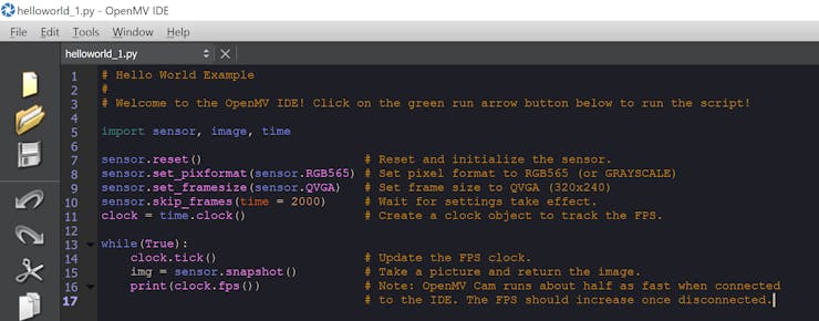
To get started we can run the example hello world provided, which configures the camera to outputs standard RGB image at QVGA resolution. On the right hand side of the IDE you will be able to see the images output from the camera.


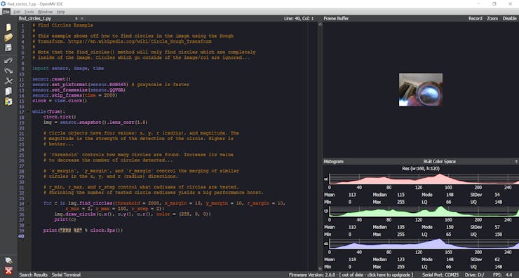
We can use this IDE to develop scripts for the OpenMV camera such as the one below which detects and identifies circles in the captured image.

Note the frame rate is lower when the camera is connected to the IDE.


We can use the scripts developed here in our Ultra96 PYNQ implementation let's take a look at how we set up the Ultra96 and PYNQ

Setting Up the Ultra96 PYNQ Image

The first thing we need to do if we have not already done it, is to download and create a PYNQ SD Card so we can run the PYNQ framework on the Ultra96.

As we want to use the Xilinx image processing overlay we should download the Ultra96 PYNQ v2.3 image.

Once you have this image creating a SD Card is very simple, extract the ISO image from the compressed file and write it to a SD Card. To write the ISO image to the SD Card we need a program such a etcher or win32 disk imager.

With a SD Card available we can then boot the Ultra96 and connect to the PYNQ framework using either

  • Use a USB Ethernet connection over the MicroUSB (upstream USB connection).
  • Connect via WiFi.
  • Use the Ultra96 as a single-board computer and connect a monitor, keyboard and mouse.

For this project I used the USB Ethernet connection.

The next thing to do is to ensure we have the necessary overlays to be able to accelerate image processing functions into the programmable logic. To to this we need to install the PYNQ computer vision overlay. 

Downloading the Image Processing Overlay

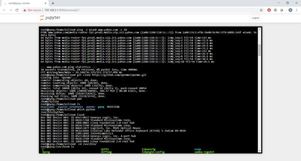
Installing this overlay is very straight forward. Open a browser window and connect to the web address of 192.168.3.1 (USB Ethernet address). This will open a log in page to the Jupyter notebooks, the password is Xilinx


Upon log in you will see the following folders and scripts


Click on new and select terminal, this will open a new terminal window in a browser window. To download and use the PYNQ Computer Vision overlays we enter the following command

sudo pip3 install --upgrade git+https://github.com/Xilinx/PYNQ-ComputerVision.git
 

Once these are downloaded if you look back at the Jupyter home page you will see a new directory called pynqOpenCV.


Using these Jupyter notebooks we can test the image processing performance when we accelerate OpenCV functions into the programmable logic.


Typically the hardware acceleration as can be seen in the image above greatly out performs implementing the algorithm in SW.

Of course we can call this overlay from our own Jupyter notebooks


Setting Up the OpenMV Camera in PYNQ

The next step is to configure the Ultra96 PYNQ instance to be able to control the OpenMV camera using its APIs. We can obtain these by downloading the OpenMV git repo using the command below in a terminal window on the Ultra96.

git clone https://github.com/openmv/openmv
 

Once this is downloaded we need to move the file pyopenmv.py

From openmv/tools

To /usr/lib/python3.6

This will allow us to control the OpenMV camera from within our Jupyter applications.

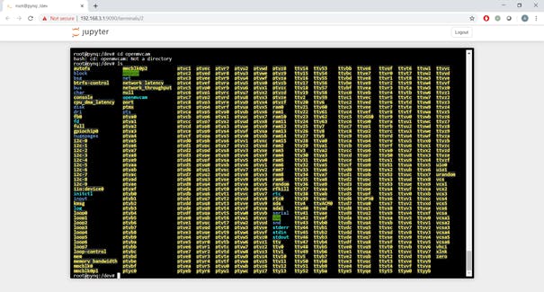
To be able to do this we need to know which serial port the OpenMV camera enumerates as. This will generally be ttyACM0 or ttyACM1 we can find this out by doing a LS of the /dev directory


Now we are ready to begin working with the OpenMV camera in our applications let's take a look at how we set it up our Jupyter Scripts


Initial Test of OpenMV Camera

The first thing we need to do in a new Jupyter notebook is to import the necessary packages. This includes the pyopenmv as we just installed.

We will alos be importing numpy as the image is returned as a numpy array so that we can display it using numpy functionality.

import pyopenmvimport timeimport sysimport numpy as np 

The first thing we need to do is define the script we developed in the IDE, for the "first light" with the PYNQ and OpenMV we will use the hello world script to obtain a simple image.

script = """

# Hello World Example

#

# Welcome to the OpenMV IDE! Click on the green run arrow button below to run the script!

import sensor, image, time

import pyb

sensor.reset()                      # Reset and initialize the sensor.

sensor.set_pixformat(sensor.RGB565) # Set pixel format to RGB565 (or GRAYSCALE)

sensor.set_framesize(sensor.QVGA)   # Set frame size to QVGA (320x240)

sensor.skip_frames(time = 2000)     # Wait for settings take effect.

clock = time.clock()                # Create a clock object to track the FPS.

red_led = pyb.LED(1)

red_led.off()

red_led.on()

while(True):

   clock.tick() 

   img = sensor.snapshot()         # Take a picture and return the image.

"""

Once the script is defined the next thing we need to do is connect to the OpenMV camera and download the script.


portname = "/dev/ttyACM0"

connected = False

pyopenmv.disconnect()

for i in range(10):

   try:

       # opens CDC port.

       # Set small timeout when connecting

       pyopenmv.init(portname, baudrate=921600, timeout=0.050)

       connected = True

       break

   except Exception as e:

       connected = False

       sleep(0.100)

if not connected:

   print ( "Failed to connect to OpenMV's serial port.\n"

           "Please install OpenMV's udev rules first:\n"

           "sudo cp openmv/udev/50-openmv.rules /etc/udev/rules.d/\n"

           "sudo udevadm control --reload-rules\n\n")

   sys.exit(1)

# Set higher timeout after connecting for lengthy transfers.

pyopenmv.set_timeout(1*2) # SD Cards can cause big hicups.

pyopenmv.stop_script()

pyopenmv.enable_fb(True)

pyopenmv.exec_script(script)

Finally once the script has been downloaded and is executing, we want to be able to read out the frame buffer. This Cell below reads out the framebuffer and saves it as a jpg file in the PYNQ file system.


running = True

import numpy as np

from PIL import Image

from matplotlib import pyplot as plt

while running:

   fb = pyopenmv.fb_dump()

   if fb != None:

       img = Image.fromarray(fb[2], 'RGB')

       img.save("frame.jpg")

       img = Image.open("frame.jpg")

       img

       time.sleep(0.100)


When I ran this script the first light image below was received of me working in my office.


Having achieved this the next step is to start working with advanced scripts in the PYNQ Jupyter notebook. using the same approach as above we can redefine scripts which can be used for different processing including

script = """

import sensor, image, time

sensor.reset() # Initialize the camera sensor.

sensor.set_pixformat(sensor.GRAYSCALE) # or sensor.RGB565

sensor.set_framesize(sensor.QQVGA) # or sensor.QVGA (or others)

sensor.skip_frames(time = 2000) # Let new settings take affect.

sensor.set_gainceiling(8)

clock = time.clock() # Tracks FPS.

while(True):

   clock.tick() # Track elapsed milliseconds between snapshots().

   img = sensor.snapshot() # Take a picture and return the image.

   # Use Canny edge detector

   img.find_edges(image.EDGE_CANNY, threshold=(50, 80))

   # Faster simpler edge detection

   #img.find_edges(image.EDGE_SIMPLE, threshold=(100, 255))

   print(clock.fps()) # Note: Your OpenMV Cam runs about half as fast while

"""

For Canny edge detection when imaging a MiniZed Board


Alternatively we can also extract key points from images for tracking in subsequent images.

script = """

import sensor, time, image

# Reset sensor

sensor.reset()

# Sensor settings

sensor.set_contrast(3)

sensor.set_gainceiling(16)

sensor.set_framesize(sensor.VGA)

sensor.set_windowing((320, 240))

sensor.set_pixformat(sensor.GRAYSCALE)

sensor.skip_frames(time = 2000)

sensor.set_auto_gain(False, value=100)

def draw_keypoints(img, kpts):

   if kpts:

       print(kpts)

       img.draw_keypoints(kpts)

       img = sensor.snapshot()

       time.sleep(1000)

kpts1 = None

# NOTE: uncomment to load a keypoints descriptor from file

#kpts1 = image.load_descriptor("/desc.orb")

#img = sensor.snapshot()

#draw_keypoints(img, kpts1)

clock = time.clock()

while (True):

   clock.tick()

   img = sensor.snapshot()

   if (kpts1 == None):

       # NOTE: By default find_keypoints returns multi-scale keypoints extracted from an image pyramid.

       kpts1 = img.find_keypoints(max_keypoints=150, threshold=10, scale_factor=1.2)

       draw_keypoints(img, kpts1)

   else:

       # NOTE: When extracting keypoints to match the first descriptor, we use normalized=True to extract

       # keypoints from the first scale only, which will match one of the scales in the first descriptor.

       kpts2 = img.find_keypoints(max_keypoints=150, threshold=10, normalized=True)

       if (kpts2):

           match = image.match_descriptor(kpts1, kpts2, threshold=85)

           if (match.count()>10):

               # If we have at least n "good matches"

               # Draw bounding rectangle and cross.

               img.draw_rectangle(match.rect())

               img.draw_cross(match.cx(), match.cy(), size=10)

           print(kpts2, "matched:%d dt:%d"%(match.count(), match.theta()))

           # NOTE: uncomment if you want to draw the keypoints

           #img.draw_keypoints(kpts2, size=KEYPOINTS_SIZE, matched=True)

   # Draw FPS

   img.draw_string(0, 0, "FPS:%.2f"%(clock.fps()))

"""

Circle Detection


import sensor, image, time

sensor.reset()

sensor.set_pixformat(sensor.RGB565) # grayscale is faster

sensor.set_framesize(sensor.QQVGA)

sensor.skip_frames(time = 2000)

clock = time.clock()

while(True):

   clock.tick()

   img = sensor.snapshot().lens_corr(1.8)

   # Circle objects have four values: x, y, r (radius), and magnitude. The

   # magnitude is the strength of the detection of the circle. Higher is

   # better...

   # `threshold` controls how many circles are found. Increase its value

   # to decrease the number of circles detected...

   # `x_margin`, `y_margin`, and `r_margin` control the merging of similar

   # circles in the x, y, and r (radius) directions.

   # r_min, r_max, and r_step control what radiuses of circles are tested.

   # Shrinking the number of tested circle radiuses yields a big performance boost.

   for c in img.find_circles(threshold = 2000, x_margin = 10, y_margin = 10, r_margin = 10,

           r_min = 2, r_max = 100, r_step = 2):

       img.draw_circle(c.x(), c.y(), c.r(), color = (255, 0, 0))

       print(c)

   print("FPS %f" % clock.fps())


This fusion of ability to offload processing to either the OpenMV camera or the Ultra96 programmable logic running Pynq provides the system designer with maximum flexibility.


Wrap Up

The ability to use the OpenMV camera, coupled with the PYNQ computer vision libraries along with other overlays such as the klaman filter and base overlays. We can implement algorithms which can be used to enable us to implement vision guided robotics. Using the base overlay and the Input Output processors also enables us to communicate with lower level drives, interfaces and other sensors required to implement such a solution.

Originaly posted here.
 

Read more…

Arm DevSummit 2020 debuted this week (October 6 – 8) as an online virtual conference focused on engineers and providing them with insights into the Arm ecosystem. The summit lasted three days over which Arm painted an interesting technology story about the current and future state of computing and where developers fit within that story. I’ve been attending Arm Techcon for more than half a decade now (which has become Arm DevSummit) and as I perused content, there were several take-a-ways I noticed for developers working on microcontroller based embedded systems. In this post, we will examine these key take-a-ways and I’ll point you to some of the sessions that I also think may pique your interest.

(For those of you that aren’t yet aware, you can register up until October 21st (for free) and still watch the conferences materials up until November 28th . Click here to register)

Take-A-Way #1 – Expect Big Things from NVIDIAs Acquisition of Arm

As many readers probably already know, NVIDIA is in the process of acquiring Arm. This acquisition has the potential to be one of the focal points that I think will lead to a technological revolution in computing technologies, particularly around artificial intelligence but that will also impact nearly every embedded system at the edge and beyond. While many of us have probably wondered what plans NVIDIA CEO Jensen Huang may have for Arm, the Keynotes for October 6th include a fireside chat between Jensen Huang and Arm CEO Simon Segars. Listening to this conversation is well worth the time and will help give developers some insights into the future but also assurances that the Arm business model will not be dramatically upended.

Take-A-Way #2 – Machine Learning for MCU’s is Accelerating

It is sometimes difficult at a conference to get a feel for what is real and what is a little more smoke and mirrors. Sometimes, announcements are real, but they just take several years to filter their way into the market and affect how developers build systems. Machine learning is one of those technologies that I find there is a lot of interest around but that developers also aren’t quite sure what to do with yet, at least in the microcontroller space. When we hear machine learning, we think artificial intelligence, big datasets and more processing power than will fit on an MCU.

There were several interesting talks at DevSummit around machine learning such as:

Some of these were foundational, providing embedded developers with the fundamentals to get started while others provided hands-on explorations of machine learning with development boards. The take-a-way that I gather here is that the effort to bring machine learning capabilities to microcontrollers so that they can be leveraged in industry use cases is accelerating. Lots of effort is being placed in ML algorithms, tools, frameworks and even the hardware. There were several talks that mentioned Arm’s Cortex-M55 architecture that will include Helium technology to help accelerate machine learning and DSP processing capabilities.

Take-A-Way #3 – The Constant Need for Reinvention

In my last take-a-way, I eluded to the fact that things are accelerating. Acceleration is not just happening though in the technologies that we use to build systems. The very application domain that we can apply these technology domains to is dramatically expanding. Not only can we start to deploy security and ML technologies at the edge but in domains such as space and medical systems. There were several interesting talks about how technologies are being used around the world to solve interesting and unique problems such as protecting vulnerable ecosystems, mapping the sea floor, fighting against diseases and so much more.

By carefully watching and listening, you’ll notice that many speakers have been involved in many different types of products over their careers and that they are constantly having to reinvent their skill sets, capabilities and even their interests! This is what makes working in embedded systems so interesting! It is constantly changing and evolving and as engineers we don’t get to sit idly behind a desk. Just as Arm, NVIDIA and many of the other ecosystem partners and speakers show us, technology is rapidly changing but so are the problem domains that we can apply these technologies to.

Take-A-Way #4 – Mbed and Keil are Evolving

There are also interesting changes coming to the Arm toolchains and tools like Mbed and Keil MDK. In Reinhard Keil’s talk, “Introduction to an Open Approach for Low-Power IoT Development“, developers got an insight into the changes that are coming to Mbed and Keil with the core focus being on IoT development. The talk focused on the endpoint and discussed how Mbed and Keil MDK are being moved to an online platform designed to help developers move through the product development faster from prototyping to production. The Keil Studio Online is currently in early access and will be released early next year.

(If you are interested in endpoints and AI, you might also want to check-out this article on “How Do We Accelerate Endpoint AI Innovation? Put Developers First“)

Conclusions

Arm DevSummit had a lot to offer developers this year and without the need to travel to California to participate. (Although I greatly missed catching up with friends and colleagues in person). If you haven’t already, I would recommend checking out the DevSummit and watching a few of the talks I mentioned. There certainly were a lot more talks and I’m still in the process of sifting through everything. Hopefully there will be a few sessions that will inspire you and give you a feel for where the industry is headed and how you will need to pivot your own skills in the coming years.

Originaly posted here

Read more…

by Singapore University of Technology and Design

Internet-of-Things (IoT) such as smart home locks and medical devices, depend largely on Bluetooth low energy (BLE) technology to function and connect across other devices with reduced energy consumption. As these devices get more prevalent with increasing levels of connectivity, the need for strengthened security in IoT has also become vital.

A research team, led by Assistant Professor Sudipta Chattopadhyay from the Singapore University of Technology and Design (SUTD), wit team members from SUTD and the Institute for Infocomm Research (I2R), designed and implemented the Greyhound framework, a tool used to discover SweynTooth—a critical set of 11 cyber vulnerabilities.

Their study was presented at the USENIX Annual Technical Conference (USENIX ATC) on 15 to 17 July 2020 and they have been invited to present at the upcoming Singapore International Cyber Week (SICW) in October 2020.

These security lapses were found to affect devices by causing them to crash, reboot or bypass security features. At least 12 BLE based devices from eight vendors were affected, including a few hundred types of IoT products including pacemakers, wearable fitness trackers and home security locks.

The SweynTooth code has since been made available to the public and several IoT product manufacturers have used it to find security issues in their products. In Singapore alone, 32 medical devices reported to be affected by SweynTooth and 90% of these device manufacturers have since implemented preventive measures against this set of cyber vulnerabilities.

Regulatory agencies including the Cyber Security Agency and the Health Sciences Authority in Singapore as well as the Department of Homeland Security and the Food and Drug Administration in the United States have reached out to the research team to further understand the impact of these vulnerabilities.

These agencies have also raised public alerts to inform medical device manufacturers, healthcare institutions and end users on the potential security breach and disruptions. The research team continues to keep them updated on their research findings and assessments.

Beyond Bluetooth technology, the research team designed the Greyhound framework using a modular approach so that it could easily be adapted for new wireless protocols. This allowed the team to test it across the diverse set of protocols that IoTs frequently employ. This automated framework also paves new avenues in the testing security of more complex protocols and IoTs in next-generation wireless protocol implementations such as 5G and NarrowBand-IoT which require rigorous and systematic security testing.

"As we are transitioning towards a smart nation, more of such vulnerabilities could appear in the future. We need to start rethinking the device manufacturing design process so that there is limited reliance on communication modules such as Bluetooth to ensure a better and more secure smart nation by design," explained principal investigator Assistant Professor Sudipta from SUTD.

Originally posted HERE.

Read more…

When you’re in technology, you have to expect change. Yet, there’s something to the phrase “the more things change, the more they stay the same.” For instance, I see in the industrial internet of things (IIoT) a realm that’ll dramatically shape the future - how we manufacture, the way we run our factories, workforce needs – but the underlying business goals are the same as always.

Simply put, while industrial enterprise initiatives may change, financial objectives don’t – and they’re still what matter most. That’s why IIoT is so appealing. While the possibilities of smart and connected operations, sites and products certainly appeal to the dreamer and innovator, the clear payoff ensures that it’s a road even the most pragmatic decision-maker will eagerly follow.

The big three
When it comes to industrial enterprises, IIoT addresses the “big three” financial objectives head on. The technology maximizes revenue growth, reduces operating expense and increases asset efficiency.

IIoT does this in numerous ways. It yields invaluable operational intelligence, like real-time performance management data, to reduce manufacturing costs, increase flexibility and enable agility. When it comes to productivity, connected digital assets can empower a workforce with actionable insights to improve productivity and quality, even prevent safety and compliance issues.

For example, recognizing defects in a product early on can save time, materials, staff hours and possibly even a company’s reputation.

Whether on or off the factory floor, IIoT can be used to optimize asset efficiency. With real-time monitoring, diagnostics and analytics, downtime can be reduced or avoided. Asset utilization can also be evaluated and maximized. Think applications like equipment health monitoring, predictive maintenance, the ability to provide augmented 3D instructions for complex repairs. And, you can also scale production more precisely via better control over processes and inventory.

All of this accelerates time to market; another key benefit of IIoT and long held business goal.

Why is 5G important for IIoT and augmented reality (AR)?
As we look at the growing need to connect more devices, more sensors and install things like real-time cameras for doing analytics, there is growing stress and strain that is brought into industrial settings. We have seen the need to increase connectivity while having greater scalability, performance, accessibility, reliability, and broader reach with a lower cost of ownership become much more important. This is where 5G can make a real difference.

Many of our customers have seen what we are doing with augmented reality and the way that PTC can help operators service equipment. But in the not so distant future, the way that people interact with robotics, for example, will change. There will be real-time video to do spatial analytics on the way that people are working with man and machines and we’ll be able to unlock a new level of intelligence with a new layer of connectivity that helps drive better business outcomes.

Partner up
It sounds nice but the truth is, a lot of heavy lifting is required to do IIoT right. The last thing you want to do is venture into a pilot, run into problems, and leave the C-suite less than enthused with the outcome. And make no mistake, there’s a lot potential pitfalls to be aware of.

For instance, lengthy proof of concept periods, cumbersome processes and integrations can slow time to market. Multiple, local integrations can be required when connectivity and device management gets siloed. If not done right, you may only gain limited visibility into devices and the experience will fall short. And, naturally, global initiatives can be hindered by high roaming costs and deployment obstacles.

That said, you want to harness best of breed providers, not only to realize the full benefits of Industry 4.0, but to set yourself up with a foundation that’ll be able to harness 5G developments. You need a trusted IoT partner, and because of the sophistication and complexity, it takes an ecosystem of proven innovators working collaboratively.

That’s why PTC and Ericsson are partners.

Doing what’s best
Ericsson unlocks the full value of global cellular IoT connectivity and provides on-premise solutions. PTC offers an industrial IoT platform that’s ready to configure and deploy, with flexible connectivity and capabilities to build solutions without manual coding.

Drilling down a bit further, Ericsson’s IoT Accelerator can connect and manage billions of devices and millions of applications easily, seamlessly and globally. PTC’s IoT solutions digitalize processes and products, combining the physical and digital worlds seamlessly.

And with wireless connectivity, we can deploy a lot of new technology – from augmented reality to artificial intelligence applications – without having to think about the time and cost of creating fixed infrastructures, running wires, adding network capacity and more.

According ABI Research, organizations that embrace Industry 4.0 and private cellular have the potential to improve gross margins by 5-13% in factory and warehouse operations. Manufacturers can expect a 10x return on their investment. And with 4.3 billion wireless connections in smart factories anticipated by 2030, it’s clear where things are headed.

By focusing on what we each do best, PTC and Ericsson is able to do what’s best for our customers. We can help them build and scale global cellular IoT deployments faster and gain a competitive advantage. They can reap the advantages of Industry 4.0 and create that path to 5G, future-proofing their operations and enjoying such differentiators as network slicing, edge computing and high-reliability, low latency communications.

Further, with our histories of innovation, customers are assured they’ll be supported in the future, remaining out front with the ability to adapt to change, grow and deliver on financial objections.

Editor's Note: This post was originally published by Steve Dertien, Chief Technology Officer for PTC, on Ericsson's website, and is part of a joint content effort with Kiva Allgood, head of IoT for Ericsson. To view Steve's original, please click here. To read Kiva's complementary post, please click here.

Read more…

A scientist from Russia has developed a new neural network architecture and tested its learning ability on the recognition of handwritten digits. The intelligence of the network was amplified by chaos, and the classification accuracy reached 96.3%. The network can be used in microcontrollers with a small amount of RAM and embedded in such household items as shoes or refrigerators, making them 'smart.' The study was published in Electronics.

Today, the search for new neural networks that can operate on microcontrollers with a small amount of random access memory (RAM) is of particular importance. For comparison, in ordinary modern computers, random access memory is calculated in gigabytes. Although microcontrollers possess significantly less processing power than laptops and smartphones, they are smaller and can be interfaced with household items. Smart doors, refrigerators, shoes, glasses, kettles and coffee makers create the foundation for so-called ambient intelligece. The term denotes an environment of interconnected smart devices. 

An example of ambient intelligence is a smart home. The devices with limited memory are not able to store a large number of keys for secure data transfer and arrays of neural network settings. It prevents the introduction of artificial intelligence into Internet of Things devices, as they lack the required computing power. However, artificial intelligence would allow smart devices to spend less time on analysis and decision-making, better understand a user and assist them in a friendly manner. Therefore, many new opportunities can arise in the creation of environmental intelligence, for example, in the field of health care.

Andrei Velichko from Petrozavodsk State University, Russia, has created a new neural network architecture that allows efficient use of small volumes of RAM and opens the opportunities for the introduction of low-power devices to the Internet of Things. The network, called LogNNet, is a feed-forward neural network in which the signals are directed exclusively from input to output. Its uses deterministic chaotic filters for the incoming signals. The system randomly mixes the input information, but at the same time extracts valuable data from the information that are invisible initially. A similar mechanism is used by reservoir neural networks. To generate chaos, a simple logistic mapping equation is applied, where the next value is calculated based on the previous one. The equation is commonly used in population biology and as an example of a simple equation for calculating a sequence of chaotic values. In this way, the simple equation stores an infinite set of random numbers calculated by the processor, and the network architecture uses them and consumes less RAM.

7978216495?profile=RESIZE_584x

The scientist tested his neural network on handwritten digit recognition from the MNIST database, which is considered the standard for training neural networks to recognize images. The database contains more than 70,000 handwritten digits. Sixty-thousand of these digits are intended for training the neural network, and another 10,000 for network testing. The more neurons and chaos in the network, the better it recognized images. The maximum accuracy achieved by the network is 96.3%, while the developed architecture uses no more than 29 KB of RAM. In addition, LogNNet demonstrated promising results using very small RAM sizes, in the range of 1-2kB. A miniature controller, Atmega328, can be embedded into a smart door or even a smart insole, has approximately the same amount of memory.

"Thanks to this development, new opportunities for the Internet of Things are opening up, as any device equipped with a low-power miniature controller can be powered with artificial intelligence. In this way, a path is opened for intelligent processing of information on peripheral devices without sending data to cloud services, and it improves the operation of, for example, a smart home. This is an important contribution to the development of IoT technologies, which are actively researched by the scientists of Petrozavodsk State University. In addition, the research outlines an alternative way to investigate the influence of chaos on artificial intelligence," said Andrei Velichko.

Originally posted HERE.

by Russian Science Foundation

Image Credit: Andrei Velichko


Read more…

By: Tom Jeltes, Eindhoven University of Technology

The Internet of Things (IoT) consists of billions of sensors and other devices connected to each other via internet, all of which need to be protected against hackers with malicious purposes. A low-cost and energy efficient solution for the security of IoT devices uses the unique characteristics of the built-in memory chips. Ph.D. candidate Lieneke Kusters investigated how to make optimal use of the chip's digital fingerprint to generate a security key.

The higher the number of devices connected to each other via the Internet of Things, the greater the risk that malicious hackers might gain access to important information, or even take over entire systems. Quite apart from all kinds of privacy issues, it's not hard to imagine that that someone who, for example, has control over temperature sensors in a chemical or nuclear plant, could cause serious damage.

 To prevent problems like these from occurring, each IoT device needs to be able, as it were, to show an identity document—"authentication," in professional terms. Normally, speaking, this is done with a kind of password, which is sent in encrypted form to the person who is communicating with the device. The security key needed for that has to be stored in the IoT device one way or another, Lieneke Kusters explains. "But these are often small and cheap devices that aren't supposed to use much energy. To safely store a key in these devices, you need extra hardware with constant power supply. That's not very practical."

Digital fingerprint

There is a different way: namely by deducing the security key from a unique physical characteristic of the memory chip (Static Random-Access Memory, or SRAM) that can be found in practically every IoT device. Depending on the random circumstances during the chip's manufacturing process, the memory locations have a random default value of 0 or 1.

"That binary code which you can read out when activating the chip, constitutes a kind of digital fingerprint of the device," says Kusters, who gained her doctorate at the Information and Communication Theory Laboratory at the TU/e department of Electrical Engineering. This fingerprint is known as a Physical Unclonable Function (PUF). "The Eindhoven-based company Intrinsic ID sells digital security based on SRAM-PUFs. I collaborated with them for my doctoral research, during which I focused on how to generate, in a reliable way, a key from that digital fingerprint that is as long as possible. The longer, the safer."

The major advantage of security keys based on SRAM-PUFs is that the key exists only at the moment when authentication is required. "The device restarts itself to read out the SRAM-PUF and in doing so creates the key, which subsequently gets erased immediately after use. That makes it all but impossible for an attacker to steal the key."

Noise and reliability

But that's not the entire story, because some bits of the SRAM do not always have the same value during activation, Kusters explains. Ten to fifteen percent of the bits turn out not to be determined, which makes the digital fingerprint a bit fuzzy. How do you use that fuzzy fingerprint to make a key of the highest possible complexity that nevertheless still fits into the receiving lock—practically—each time?

"What you want to prevent is that the generated key won't be recognized by the receiving party as a consequence of the 'noise' in the SRAM-PUF," Kusters explains. "It's alright if that happens one in a million times perhaps, preferably less often." The probability of error is smaller with a shorter key, but such a key is also easier to guess for people with bad intentions. "I've searched for the longest reliable key, given a certain amount of noise in the measurement. It helps if you store extra information about the SRAM-PUF, but that must not be of use to a potential attacker. My thesis is an analysis of how you can reach the optimal result in different situations with that extra information."

Originaly posted here.


Read more…

7811924256?profile=RESIZE_400x


CLICK HERE TO DOWNLOAD

This complete guide is a 212-page eBook and is a must read for business leaders, product managers and engineers who want to implement, scale and optimize their business with IoT communications.

Whether you want to attempt initial entry into the IoT-sphere, or expand existing deployments, this book can help with your goals, providing deep understanding into all aspects of IoT.

CLICK HERE TO DOWNLOAD

Read more…

Edge Products Are Now Managed At The Cloud

Now more than ever, there are billions of edge products in the world. But without proper cloud computing, making the most of electronic devices that run on Linux or any other OS would not be possible.

And so, a question most people keep asking is which is the best Software-as-a-service platform that can effectively manage edge devices through cloud computing. Well, while edge device management may not be something, the fact that cloud computing space is not fully exploited means there is a lot to do in the cloud space.

Product remote management is especially necessary for the 21st century and beyond. Because of the increasing number of devices connected to the internet of things (IoT), a reliable SaaS platform should, therefore, help with maintaining software glitches from anywhere in the world. From smart homes, stereo speakers, cars, to personal computers, any product that is connected to the internet needs real-time protection from hacking threats such as unlawful access to business or personal data.

Data being the most vital asset is constantly at risk, especially if individuals using edge products do not connect to trusted, reliable, and secure edge device management platforms.

Bridges the Gap Between Complicated Software And End Users

Cloud computing is the new frontier through which SaaS platforms help manage edge devices in real-time. But something even more noteworthy is the increasing number of complicated software that now run edge devices at homes and in workplaces.

Edge device management, therefore, ensures everything runs smoothly. From fixing bugs, running debugging commands to real-time software patch deployment, cloud management of edge products bridges a gap between end-users and complicated software that is becoming the norm these days.

Even more importantly, going beyond physical firewall barriers is a major necessity in remote management of edge devices. A reliable Software-as-a-Service, therefore, ensures data encryption for edge devices is not only hackproof by also accessed by the right people. Moreover, deployment of secure routers and access tools are especially critical in cloud computing when managing edge devices. And so, developers behind successful SaaS platforms do conduct regular security checks over the cloud, design and implement solutions for edge products.

Reliable IT Infrastructure Is Necessary

Software-as-a-service platforms that manage edge devices focus on having a reliable IT infrastructure and centralized systems through which they can conduct cloud computing. It is all about remotely managing edge devices with the help of an IT infrastructure that eliminates challenges such as connectivity latency.

Originally posted here

Read more…

Embedded Linux or RTOS: For IoT

by Tirichlabs

Embedded Linux utilizes Linux kernel for an embedded device, but it is quite different from the standard Linux OS. Its application to embedded systems is motivated by the availability of device support, file-systems, network connectivity, and UI support. It is a customized version of Linux for embedded systems, consequently having a much smaller size and minimal features and requires less processing power. Based on embedded system requirements, the Linux kernel is modified and optimized. Such embedded Linux can only run device-specific purpose-built applications.

The Real-Time Operating System (RTOS) with minimal code is used for such applications where least and fix processing time is required. RTOS is a time-sharing system based on clock interrupts that implement priority sequences to execute a process. In the event of a high priority, interrupt is generated by the system, the running low priority processes are stopped and the interrupt is served. The real-time operating system requires less operational memory and synchronizes the processes in such a way they can communicate with each other hence resources can be used efficiently without wastage of time.


COMPARISON

Size

The major difference between Embedded Linux and RTOS is in their sizes. RTOS running on an AVR requires approximately 4.4 kilobytes of ROM. Embedded Linux, on the other hand, is relatively larger. The kernel can be stripped of which are not required and even with that, the footprint is generally measured in megabytes.

Embedded Linux RAM requirement is in order of few megabytes. In practical applications, it requires more than that because some other tasks run under these Linux kernels. RTOS has much smaller memory requirements than Linux. A very simple setup, running two tasks, a scheduler, a queue for communication and a semaphore on an 8-bit architecture would use in the vicinity of 200 bytes.

Scheduler

The scheduler in an RT-system is important to ensure that tasks complete in a fixed time. Compared to a regular scheduler for a general-purpose system, it is not the main task of the scheduler to ensure ’fair’ distribution of CPU-time. A common technique is simply to let the task with the highest priority run before all tasks with lower priority. It works fine for a soft real-time system but for hard real-time, the system must provide a better guarantee.

RTOS scheduler

RTOS uses the highest priority first scheduler. It means that the task having the highest priority is always running. This is achieved by having a preemptive scheduler that at a tick-interrupt decides if the currently running task is allowed to continue executing or it needs to be switched for another task based on priority. The scheduler uses the priority to schedule the task with the highest priority. Tasks having the same priority are given a “fair” process time. This schedular allows us to achieve soft real-time but it is difficult to achieve hard real-time by not having any kind of deadline-based scheduling.

For this purpose, there are choices of having a preemptive or a cooperative scheduler. In preemptive mode, a task can be preempted unlike in cooperative mode where it’s up to all tasks to give away the CPU “often” enough so higher priority tasks get to run. Typical RTOS real-time kernel achieves scheduler latencies from zero to a few microseconds.

Embedded Linux scheduler

In Embedded Linux, there are more choices to choose the scheduler. The modular of Embedded Linux allows to change different parts of the system. A simple insmod gives the possibility to change the scheduler. There are a couple of schedulers designed for different things.

First of all, it has a basic highest priority first scheduler that uses the priority of a task and schedules it first. Embedded Linux also implements the Earliest deadline first which uses the periodic feature of Embedded Linux. Assuming that the deadline for every task is when it is next to be run again one can implement a fast EDF. In theory, it is optimal since it can schedule tasks to 100% CPU-usages. In practice, it is not the same due to some overheads. As in idle process Embedded Linux runs a usual Linux kernel and when there are no rt-tasks that can run, Linux gets to run. which can lead to starvation of Linux and thus effectively disabling Linux. But the importance of a real-time system is to run the real-time tasks this is not a big problem for the system. Typical latencies in real-time Linux schedular are in the order of tens to hundreds of microseconds.

CPU resource

Embedded Linux requires a significant amount of CPU resources, perhaps >200MIPS, 32bit processor, ideally with an MMU, 4Mb of ROM and 16MB of RAM and boot may take several seconds.

An RTOS, on the other hand, runs in less than 10Kb, on microcontrollers from 8-bit up and boot in milliseconds.

IoT Implementation of OS

Embedded Linux is often preferred for extremely low-power applications, such as sensors, run for months on batteries. The low-power nature often precludes direct IP connectivity which serves as a gateway for Internet connectivity. The gateway communicates the low-power protocol to the sensors and would translate them to IP. Linux may have an existing protocol to fulfill the requirements.

The basic requirement of an IoT device is network connectivity, typically in the form of IP via a web server. An RTOS can offer IP connectivity but have a risk to be buggy unless you examine it. For example, usually, RTOSs do not isolate the IP stack user from the IP stack itself. Network connectivity requires potentially dealing with low speed or congested links which can lead to obscure and hard-to-debug buffer handling issues when the stack is intermingled with other code. On the other hand, an embedded Linux leverages hardware separation and a widely utilized IP stack that probably has been exposed to corner cases.

Security is essential in IoT devices, which are often exposed to open Internet. A system compromise on the Internet interface is prone to intruders and information or control of the device can be hijacked. Developers can leverage native, embedded Linux features—multiuser, SELinux, and containers—to contain and limit the damage.

Linux certainly is a robust and secure OS and the system has matured in an embedded operating system. Yet one of the drawbacks is its Memory footprint when compared to a real-time operating system even though it can be trimmed down by removing tools and system services that are not required in embedded systems, it still is a large software. It simply cannot run on 8 or 16-bit MCUs and requires more onboard RAM for the Linux kernel. For example, ARM Cortex-M architecture based MCUs, which typically have only a few hundred kilobytes of RAM, and Linux cannot run on these chips.

A common engineering solution for networked systems is to use two processors in the device. In this arrangement, an 8 or 16-bit MCU is used for the sensor or actuator, while a 32-bit processor is used for the network interface which runs an RTOS. Sales of 32-bit MCUs have exploded in the last several years, and have become the largest segment of the MCU market.

ORIGINALLY POSTED HERE ON TIRICH LABS

Read more…


max0492-01-arduino-breakout-board-1024x885.jpg

When I work on a development project, I’ve become a big fan of using development boards that have the Arduino headers on them. The vast number of shields that easily connect to these headers is phenomenal. The one problem that I’ve always had though was that there is always a need to use a breadboard to test a circuit or integrate a sensor that just isn’t in an Arduino header format. The result is a wiring mess that can result in loose or missing connections.

I was recently talking with Max Maxfield and he pointed me to a really cool adapter board designed to remove these wiring jumpers to a breadboard. Max wrote about this board here but I’m so excited about this that I thought I’d add my two cents as well.

The BreadShield, which can be purchased at https://www.crowdsupply.com/loser/breadshield, adapts the Arduino headers to a linear set of header pins designed to be plugged into a breadboard. You can see in the image below that this completely removes all the extra jumpers that one would normally require which has the potential to remove quite a few jumper wires.

max0492-03-arduino-breakout-board-1024x675.jpg

When I heard about these, I purchased three assembled units for about $28 which saves me the time from having to assemble the adapter myself. DIY assembly runs for about $15 for a set of three boards. Either way, a great price to remove a bunch of wires from the workbench.

Now I’m still waiting for mine to arrive, but from the image, you can see that the one challenge to using these adapters might be adapting the height of your breadboard to your hardware stack. While this could be an issue, I keep various length spacers around the office so that I can adapt board heights and undoubtedly there will be a length that will ensure these line up properly.

You can view the original post here

Read more…

In-Circuit Emulators

Does anyone remember in-circuit emulators (ICEs)?

Around 1975 Intel came out with the 8080 microprocessor. This was a big step up from the 8008, for the 8080 had a 64k address space, a reasonable ISA, and an honest stack pointer (the 8008 had a hardware stack a mere 7 levels deep). They soon released the MDS 800, a complete computer based on the 8080, with twin 8" floppy drives. An optional ICE was available; this was, as I recall, a two-board set that was inserted in the MDS. A ribbon cable from those boards went to a small pod that could be plugged into the 8080 CPU socket of a system an engineer was developing.

The idea was that the MDS could act as the device's under test (DUT) CPU. It was rather like today's JTAG debuggers in that one could run code on the DUT, set breakpoints, collect trace data, and generally debug the hardware and software. For there was no JTAG then.

We had been developing microprocessor-based products using the 8008, but quickly transitioned to the 8080 for the increased computational power and address space. I begged my boss for the money for an MDS, which was $20k (about $100k in today's dollars), and to my surprise he let us order one. Despite slow floppies that stored only 80 KB each this tool greatly accelerated our work.

Before long ICEs were the standard platform for embedded work. Remember: this was before PCs so there were no standard desktop computers. The ICE was the computer, the IDE (such as it was) and the debugger.

In the mid-80s I was consulting and designed a, uh, "data gathering" system for our friends in Langley, VA, using multiple NSC-800 CPUs. There were few tools available for this part so I created a custom ICE that let me debug the code. Then a light bulb went on: why not sell the thing? There was practically no market for NSC-800 tools so I came up with versions for the Z80 and 8085 and slapped a $695 label on it. Most ICEs at the time cost many thousands so sales spiked.

Back then we still drew schematics on large D-size (17" x 22") vellum with a pencil. I laid out the PCBs on mylar with black tape for the tracks, as was the norm at the time.

This ICE is perhaps the design I'm most proud of in my career. It was only 17 ICs but was the epitome of an embedded system. Software replaced the usual gobs of hardware. On a breakpoint, for instance, the hardware switched from using the DUT stack to a stack on the emulator, but since the user's stack pointer could point anywhere, and the RAM in the ICE was only a few KB, the hardware masked off the upper address bits and lots of convoluted code reconstructed the user environment.

At the time ICEs advertised their breakpoints; most supported no more than a few as comparators watched the address bus for the breakpoint. My ICE used a 64k by one bit memory that mirrored the user bus. Need a breakpoint at, say, address 0x1234? The emulator set that bit in the memory true. Thus, the thing had 65K breakpoints. One of my dumbest mistakes was to not patent that, as all ICE vendors eventually copied the approach.

The trouble with tools is support. An ICE replaces the DUT CPU, and interfaces with all sorts of unknown target hardware. Though the low clock rates of the Z80 meant we initially had few problems, as we expanded the product line support consumed more and more time. Eventually I learned it was equally easy to sell a six-thousand-dollar product as a six-hundred-dollar version, so those simple first emulators were replaced by much more complex many-hundred chip versions with vast numbers of features.

But the market was changing. By the mid-90s SMT CPUs were common. These were challenging to connect to. Clock rate soared making every connection a Maxwell Law nightmare. I sold the business in 1997 and went on to other endeavors. Eventually the ICE market disappeared.

One regret from all those years is that I didn't save any of the emulator's firmware or schematics. In this business everything is ephemeral. We should make an effort to preserve some of that history.

You can view the original post on TEM here

Read more…

Industrial Prototyping for IoT

I-Pi SMARC.jpg

ADLINK is a global leader in edge computing driving data-to-decision applications across industries. The company recently introduced I-Pi SMARC for Industrial IoT prototyping.

-       AdLInk I-Pi SMARC consists of a simple carrier paired with a SMARC Computer on Module

-       SMARC Modules are available from entry level PX30 Rockchip to top of the line Intel Apollo Lake.

-       SMARC modules are specifically designed for typical industrial embedded applications that require long life, high MTBF and strict revision control.

-       Use popular off the shelve sensors and create prototypes or proof of concepts on short notice.

Additional information can be found here


Read more…

The tinyML Foundation is excited to be offering a new activity to our community: tinyML Talks webcast series. A strong line-up of speakers making 30-minute presentations will take place twice a month on Tuesdays at 8 am Pacific time to make sure that tinyML enthusiasts worldwide will have an opportunity to watch them live. Presentations and videos will be available online the day afterwards for those that were not able to join live.

View Schedule of Upcoming Talks

If you want to re-watch all talks starting March 31 or were unable to join us live, the slides and links to our YouTube Channel of the talks are posted at our tinyML Forums. Many questions were asked during the presentations but not all could be answered in the allotted time frame. The answers to some of those can be found on the tinyML Forums as well.

Read more…
RSS
Email me when there are new items in this category –

Sponsor